Some persons may ask what is actually a power supply?
To make it very simple, our laptop charger, phone charger etc are all power supply. If you cut off the head of your phone charger and connect the two wires directly to a power source, lol..x your phone will instantly damage.
Our DVD players, TV sets and other electronics have power supply.
Let's go straight to the point since we now understand what a power supply is....
Components needed..
*A step down transformer
.


*A rectifier diode


*An electrolytic capacitor

*A voltage regulator

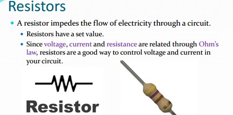
*A resistor (1k ohm)

*An LED

There are other components for advanced power supply. But this is all we need for now.
PROCEDURE..
1: Transformation
This steps down the 220volts supply to a smaller voltage say 12volts Using the step down transformer, connect the output wires to the diode which is already in a bridge form below. The wires going to the point where D1 and D3 meet while the other to where D2 and D4 meet.
2: Rectification: this is a way of converting the AC (alternating current) from the transformer to DC (direct current)
Connect your diode in a bridge form


Where the positive terminal of the diodes meets becomes the negative output while the point where the negative terminals of the diode meets becomes the positive terminal.
where D1 and D2 meet is -ve output while where D3 and D4 meet is the +ve output.
3: Purification:
This filters out the remaining AC ripples with the use of the capacitor.
You take the +ve out put of the bridge rectify to the + of the electrolytic capacitor and the -ve to the -ve of the capacitor.

4: Regulation
This is done with the use of voltage regulator.
The voltage regulator gives you the required voltage needed for your gadget
We have 78xx if you need only 5volt output like our phone chager you use 7805. This component has 3 pinouts, pin 1 is connected to ground the +ve of the capacitor or you call it input pin, pin2 is connected to ground, pin3 is the output.

You now connect your LED for power indication andyour resistor in series to pin 3, then you connect another wire from pin2 which will be your ground. See circuit diagram below


The resistor like 1k ohm.
You can use this circuit of yours to charge your phone and power other electronic gadgets.
No comments:
Post a Comment